Starting a new thread... hop[e this is OK, mods.
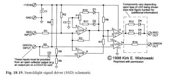
So, I've bought further into the Bruce Chubb CMR/I world with the acquisition and construction of two Searchlight Signal Driver boards to drive up to 24 bicolor LED signals. The SSD is pretty slick; it's got one resistor with series diode for the red aspect, another resistor with a series diode for the green aspect, and a trimpot to vary the duty cycle to give a fairly good yellow aspect.
I'm planning to use one, Arduino Mega 2560, for track detection and turnout position logic. With 12 blocks and 28 turnouts in this, I'll have some extra inputs.
This will talk to a second, Arduino Mega 2560, which will drive the SSD boards. 48 outputs (2 per signal) should be plenty.
Which leads me to the questions:
- The SSD board (12VDC supply) takes a pulldown on the inputs. Can I set the pinmode to OUTPUT on the second Arduino (5VDC supply) and connect the SSD inputs directly to the outputs, or should I add an additional pulldown or pullup resistor on each line?
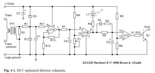
- The DCC Optimized Detector has a pulldown transistor as the output. Can I connect the DCCOD outputs (12VDC supply) directly to the first Arduino's (5VDC supply) input pins, or should I add an additional pulldown or pullup resistor on each line?